
Exploration of steel barrel flanging machine (2)
Wuhan Metal Container Factory 2 Wang Lin
There is also a horizontal double-head hydraulic flanger which is also a rolling type flanger. Its shape is similar to that of Figure 4. However, the feed movement and the headbox feeding movement are all hydraulically completed, so the structure is simpler than that of Figure 4 (using a simple hydraulic pump and hydraulic cylinder instead of a mechanical transmission and feed device such as cam feed) . The main rotary motion is still driven by the electric motor to decelerate the primary belt drive and the gear drive to drive the main pumping rotation. It has a high degree of automation, good edge accuracy, smooth transmission, low noise, and is widely used abroad. In China, due to the fact that the leakage of hydraulic components has not been solved well and the price of hydraulic oil is high, it has also limited the extent that this type of burring machine is widely used in China.
Figure 5 is a schematic diagram of the operation of the simplest vertical single-head rolling edger. The movement characteristic of the burring machine is that the barrel body is actively rotated, and the two pressure rollers are rotated by the barrel body during the burring process, and the feeding motion is realized by the radial translation of the inner pressure roller.
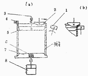
Figure 5 Vertical single-head drum flanger working principle diagram
1-external pressure roller; 2-internal pressure roller; 3-spindle; 4-wheel; 5-turntable; 6-rolling bearing; 7-tail plate; 8-cylinder
The working process of the machine is as follows: Firstly, the piston in the cylinder 8 is in the lowest position, and the tail plate 7 at the end of the piston rod is at the lowest position, and the barrel to be flanged can be placed on the tail plate. When the piston in the cylinder 8 is ascending, the tail tray 7 and the barrel are moved up until the end of the barrel contacts the axial positioning roller 4, as shown in (a) of the figure. Then, the main shaft 3 and the turntable 5 fixed thereon are rotated, and the barrel body and the tail tray 7 are driven to rotate together, and then the outer pressing roller 1 is swung to the outer edge of the barrel mouth, and the inner pressing roller 2 is Shift out of the barrel until the barrel is finished, as shown in (6).
In addition to the burring process of the barrel, the rolling type burring machine can also complete the roll and the neck of the barrel, and can also complete the burring process if the shape of the upper and lower pressing rolls is changed. Comprehensive processes such as rolling corrugation and necking. Figure 6 is a schematic diagram of the drive of a machine that can perform the integrated process of flanging and necking at the same time. Compared with the flange shown in Figure 2, the machine has a lot in common in basic principles. For example, the active roller is used for the active rotary motion, and the upper roller is oscillated by the cam mechanism to achieve the feed. The difference is that the specific structure of the cam feed mechanism is very different, and since the machine is a single-head flange, the axial control mechanism of the barrel is increased. The working principle and process of the machine are as follows:
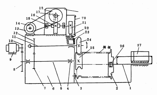
Figure 6 Horizontal single-head rolling flanger shrinking machine transmission diagram
1-tail shaft; 2-tail plate; 3-positioning roller; 4--bearing; 5--spindle; 6-frame; 7-gear; 8-gear; 9-motor; 10--gear; 12-gear; 13-motor; 14-pulley; 15-bearing; 16-worm wheel; 17-worm; 18-pulley; 19-reduction box; 20-spring; 21-cam; 22-roller; , 24-upper roller; 25-lower roller; 26--bearing; 27-cylinder
1) Axial Positioning When the piston in the cylinder 27 is in the rightmost position, the tail shaft 1 fixed to the piston rod and the tail plate supported by the bearing 26 on the tail shaft 1 are also in the rightmost position. At this time, the barrel is sleeved between the upper and lower pressing rollers 24 and 25, and the air valve is operated to make the piston left until the tail tray is fitted into the right end of the barrel, and the left end of the barrel contacts the end surface of the side roller 3. until.
2) The flanged neck motor 9 rotates the spindle 5 by the primary gear transmission (the gears 10 and 8 are meshed), so that the lower rear roller 25 fixed to the left end of the spindle 5 obtains the main rotary motion.
The motor 13 rotates the worm 17 by the primary belt drive (pulleys 14 and 18), and the worm wheel 16 engaged with the worm 17 is rotated slowly, so that the cam 21 coaxial with the worm wheel also rotates slowly. Due to the action of the spring 20, the roller 22 on the roller carriage 23 always abuts against the cam. As the cam rotates and its lift increases, the roller 22 is forced to move down and the roller carriage moves down. Moreover, since the roller frame is sleeved on the swing shaft 11, the swing shaft will swing downward about the fulcrum 1 at the left end thereof, and the upper pressing roller 24 fixed at the right end of the swing shaft is pressed downward to press the roller to realize the feed motion. .
During the downward swing of the swing shaft about the fulcrum A, the gear 12 thereon is gradually meshed with the gear 7 on the rotating main shaft to rotate the swing shaft, so that the upper press roller also obtains the main rotary motion.
Due to the active rotation of the upper and lower pressure rollers and the oscillating feed of the upper pressure roller, the barrel body is forced to rotate and locally deform, thereby completing the flanging and necking. As shown in the figure.
3) Returning the barrel When the cam 21 continues to rotate and the lift is reduced, the roller frame and the roller thereon rise under the action of the spring, the swinging shaft swings upward around the fulcrum A, and the upper pressing roller swings upward and leaves the barrel . Then, the piston in the cylinder is made to the right, the tail plate is taken out of the barrel, and the barrel can be taken out, and the working cycle ends.
In general, the rolling type flanging machine has many functions, and has strong adaptability to different metal materials and different plate thicknesses, so it is currently widely used in China. However, such machines, especially the roll-rolling type rolling and flanging machine, have the disadvantage of lower flanging accuracy than the extruded cuffing machine.
2. The squeeze type burring machine is characterized by no rotational movement, and the burring action is performed by the relative movement of the two pressure plates along the axial direction of the barrel. The relative movement of the two pressure plates is mostly achieved by hydraulic transmission, see Figure 7. During the burring process, the wall of the barrel is squeezed, and in order to assist the barrel wall to withstand the pressing force, the common tire protects the barrel wall from the periphery.
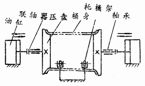
Figure 7 Schematic diagram of the extrusion flanger
Extrusion edging machines are particularly suitable for multiple crimping, such as triple rounded buckets, due to their high flanged accuracy. In addition, due to the hydraulic drive and no rotary motion, the structure is simple and the noise is small. However, when the squeezing flange is used, the wall of the barrel is subjected to a certain pressing force, so the squeeze type burring machine cannot be used for a metal barrel having a low strength, such as an aluminum barrel. It is generally applied to steel drums with a thickness of 0.6 mm or more.
Two shaped bucket cuffing machine
Since the curvature around the barrel of the shaped bucket is not the same, the flanger is complicated. Commonly used shaped bucket flanging machines are available in both slider and roll type. For the barrel with better strength, squeeze type can also be used.
1. In the slider type slider type flanging machine, the flanging action is mainly performed by a slider located inside and outside the barrel body. The principle of the slider type flange is shown in Figure 8. In the figure, the inner tube mold is fixed during the whole flange process. Its outer edge shape is the same as that of the barrel body, and the upper part is slightly tapered to facilitate the nesting of the barrel. The inner and outer slides can all along the horizontal plane. slide. When working, firstly, the barrel body is placed outside the inner tire mold, and the lower end of the barrel body is placed on the step of the inner slider, as shown in (a) of the figure. Next, slide the outer slider toward the barrel until the barrel is hung from the periphery, and then slide the inner slide out of the barrel until the barrel is finished, as shown in (b).
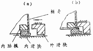
Figure 8 Schematic diagram of the slider type flanging
In order to ensure that the outer slide can slide along the radial direction of the barrel and protect the barrel from the entire outer circumference of the barrel, the outer slide must be composed of multiple pieces. Similarly, in order to allow the inner slider to slide radially along the barrel and to turn the end of the barrel outward, the inner slide should also be composed of multiple pieces. The number of inner and outer slider segments and the position of the dividing line depend on the cross-sectional shape of the barrel, and there are many options. For example, in the waist barrel flanger, the inner and outer sliders can be divided as shown in Figure 9, that is, the inner slider is divided into six pieces, and the outer slider is divided into four pieces.
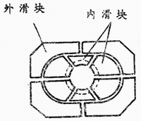
Figure 9 Schematic diagram of the inner and outer sliders of the waist barrel
The sliding of the inner and outer sliders can be achieved by a variety of mechanisms and devices. Such as crank linkage, cam mechanism, screw mechanism, ramp mechanism or hydraulic transmission and so on. In addition, since the barrel body is subjected to an upward component force during the burring process, it is easy to lift upward. In order to prevent the barrel body from being placed, the barrel body should be axially positioned and pressed. This action can also be done by various mechanisms or devices.
Figure 10 is a transmission diagram of the shaped bucket slider type flanger. In the figure, the left and right structures are symmetrical, and the left and right movements during operation are also boring, but in order to clearly express the transmission process, we will indicate the left half of the barrel to be flanged; the right half indicates the state at the end of the flange. The whole working process of the machine is described in the following four aspects.
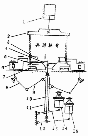
Figure 10 Shaped æ… Slider Flange Drive Legend
1-cylinder; 2-platen; 3-inner tire die; 4-cone; 5--inner slider; 6-outer slider; 7-spring; 8-fork lever; 9-_link; Mandrel; 11-sleeve; 12- hem bar; 13-upper pen; 14--cylinder; 15-cylinder
1) Feeding and axial positioning of the barrel When the piston in the hydraulic cylinder 1 is in the uppermost position, the pressure plate 2 fixed on the piston rod is in the uppermost position, and the barrel is placed under the pressure plate and sleeved The upper step of the inner tube mold 3 and the inner slider 5. Then, the piston is lowered, and the platen is lowered, and the barrel is pressed from the axial direction as shown in the left half of the figure.
2) The piston in the bucket hydraulic cylinder 14 descends, causing the upper swing lever 13 to swing downward about the fulcrum of its left end, and the upper end of the fork lever 8 swings toward the bucket body by the action of the sleeve 11 and the link 9. Since the upper end of the fork lever is hinged to the outer slider 6, the outer slider 6 is also slid in the direction of the barrel until the barrel is hooped from the periphery.
3) Flanging causes the piston in the hydraulic cylinder 15 to descend, the hem rod 12 swings downward about its left end fulcrum, and the mandrel 10 hingedly connected with the middle portion of the hem rod moves downward, and the cone fixed at the upper end of the mandrel (cone) The body or pyramid) 4 must move down. Through the action of the inner slider 5 and the cone of the cone, the inner slide is forced to slide horizontally outside the barrel, causing the barrel to complete the flange, as shown in the right Half.
4) Returning the barrel to make the piston in the hydraulic cylinder 14 ascend, through the action of the upper swing rod 13, the sleeve 11 and the fork lever, the outer slider slides outward and leaves the barrel to return to the original position. At the same time, the piston in the cylinder 15 is advanced, the hem is swung upward, the mandrel and the cone are raised, and the inner slider slides inwardly under the action of the spring 7 to return to the original position. Then, the piston in the cylinder 1 goes up, the pressure plate rises, and the flanged body can be taken out.
The flanging of the shaped keg can also be achieved with a flanging device on the punch. The principle of the flange is the same as that of the slider flange described above, and the action of the outer drum and the inner slider of the flange device are all performed by the movement of the punch on the punch.
2. The rolling type special-shaped rolling type cuffing machine is the same as the round barrel rolling type cuffing machine, and the barrel body and the inner and outer pressing rolls are rotated when the flange is turned. The difference is that the inner and outer pressure rollers of the profiled barrel rolling type cuffing machine must also be contoured with the rotating barrel body.
Grill pans provide a great way to mimic the experience of outdoor grilling. They`re especially useful for people who live in apartments. However, using a Grill Pan is different than cooking with regular stovetop pans. There are several things you need to do so your food cooks properly and has char marks and a grilled taste. Ultimately, by preparing your pan and food, taking steps to properly gill your food, and seasoning and storing your pan, you`ll be able to use your grill pan to its full potential.


Aluminum Grill Pan,Coating Forged Aluminum Grill Pan,Forged Aluminum Grill Pan,Coating Grill Pan
OSFE INDUSTRIAL CO.,LTD , http://www.1758cookware.com